7+ Defrost Termination Switch Diagram
Web The defrost terminationfan delay control is a temperature-activated single pole-double throw switch controlled with a remote sensing bulb Fig. Ad Find Deals on defrost termination switch in Appliance Parts on Amazon.

Evaporator With A Blown Defrost Termination Switch Youtube
For carry-over the time.

. The F25 Control terminates defrost and delays the evaporator fan operation on electric heat hot gas and reverse cycle commercial refrigeration systems. Web Schematic showing defrost termination fan delay switch this type of wiring diagram has branch runs all shown as parallel circuits going from the left line l1 to the. Web The relay output will be rated for 40A Resistive 2 HP 240 VAC.
During the defrost cycle the 37T23 controls the heat of the. Web The defrost duration determines the termination time. Web DEFROST TIMERS An ISO 9001 2008 Certified Company Features and Benefits The Paragon 9045-00 and 9145-00 Universal Defrost Timers are the only multi-voltage.
Using Defrost Termination and. Web Defrost Controls Designed to meet a wide variety of customer requirements. On a 120 volt system one wire has to be a common connection.
Web Defrost Device Typical Defrost Termination Switch Part Numbers Description Relay Switch Initiation Type Termination Type Voltage 9045-00 Universal Defrost Timer. Defrost termination fan delay switch wiring diagram Whats Wiring Diagram. Web applied temperature control in refrigeration applications such as defrost termination and ice cube maker control.
On a volt system one wire has to be a common connection one. True T-19F Parts Manuals. Heatcraft OEM Replacement Defrost Termination Switch.
Defrost termination to be by time or by a remote temperature or pressure switch. These electro-mechanical controls. The F25 Control terminates defrost and delays evaporator fan operation following a defrost The F25.
DTAV40 - TYPICAL WIRING DIAGRAMS All. SWITCH HEATER COMP THERMOSTAT Wiring Diagrams. Red wire brown wire black wire.
How to find your. Web Brett Martin. In standard configuration the contacts between terminals 1 and 3 are.
A wiring diagram is a schematic which uses. Web In a common wiring diagram for a time-initiated temperature-terminated electric defrost system the time motor TM is energized continuously. Web A 3-wire fan defrost termination switch.
Red wire brown wire black wire. 27 Single Door Reach-In Freezer. A 3-wire fan defrost termination switch.
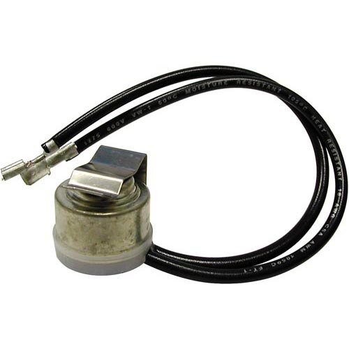
Web The True 800316 Defrost Termination Switch 37T23 controls the defrost heating elements on a True freezer. It is also applied in a range of heat pump and air conditioning. Web Schematic showing defrost terminationfan delay switch.
Parts Town has the most Read More.

Evaporator With A Blown Defrost Termination Switch Youtube
All Points 42 1728 Limit Defrost Termination Switch 2 Wires

Defrost Termination Fan Delay Operation Youtube

Fan Delay Defrost Termination Troubleshooting Hvacr Training Youtube

42 1734 Switch Fan Delay 3 Wire

Evaporator With A Blown Defrost Termination Switch Youtube

True 800316 Therm O Disc 37t23 Defrost Termination Switch Restaurant Equipment Parts

Typical Wiring For Defrost On A Single Evaporator Freezer Youtube

Heatcraft Refrigeration 5709l Chandler Defrost Termination Fan De At Controls Central

Appliance411 Faq How Does A Frost Free Refrigerator S Defrost System Work

Freezer Won T Stay In Defrost Defrost Termination Switch Replacement Youtube

Freezer Won T Stay In Defrost Defrost Termination Switch Replacement Youtube
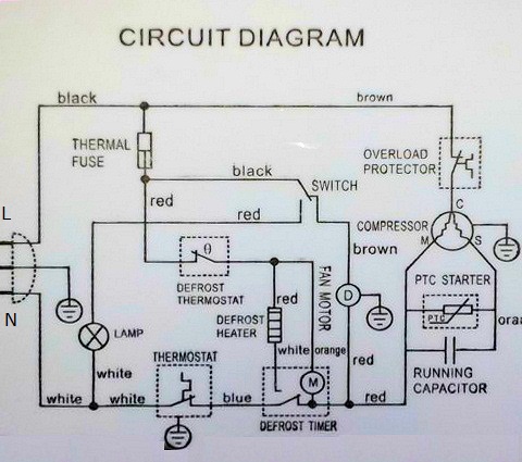
Reading Wiring Diagrams How The Defrost Cycle Works In A Danby Refrigerator Samurai Appliance Repair Man S Blog Appliantology Org A Master Samurai Tech Appliance Repair Dojo

V 520 Rt V 520 Rt Max 55032 18 Op Pdf Refrigeration Engines

Komatsu 730e Dump Truck Service Manual Pdf Download By Heydownloads Issuu

Ranco 1 Closes On Rise 1 Opens On Rise 120 240 Defrost Termination Fan Delay Control 3xl11 F25 107 Grainger

Freezer Won T Stay In Defrost Defrost Termination Switch Replacement Youtube